


MODULAR RECTIFIERS AIR COOLING

MODULAR RECTIFIERS AIR COOLING
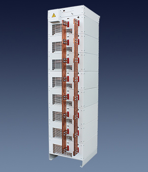
The fundamental characteristic of the Powerel rectifier is its totally modular construction. Each module is independent and complete with all its functions and can provide a maximum output of 16 kW. Up to 32 modules can be connected in parallel, thus achieving very high currents and powers.
Technical Data
| Power supply | Threephase 400 VAC without neutral |
| Currents supplied for module | MAX 1000 A |
| Voltages supplied for module | MAX 400 V |
| Power for module | MAX 16 kW |
| Controlled modules (parallel or series) |
MAX 32 |
| Modules for tower | Max 10, suggested 6 for transport limit |
| Standard efficiency | 85% |
| Maximum efficiency | 88% |
| Range power adjustment | 2% ÷ 100% |
| Ripple | <= 2% (<1% on demand) |
| Dielectric insulation | 2500 V RMS |
| Serial connection | Ethernet: Profinet, Modbus-TCP, Serial port: Profibus, RS485 Modbus-RTU, Analogycal: 0-10V, 0-20mA, 4-20mA |
| Max environment themperature | 40° C |
| Maximum humidity | 85% |
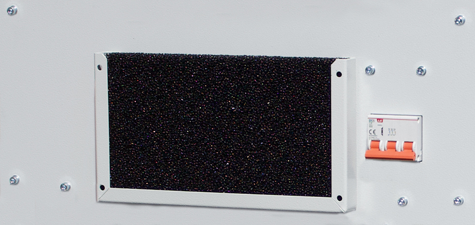
| Protection and maintenance | Short circuit, over temperature, electronic cards tropicalisation, epoxy painted or zinc plated metal parts, air filters, electronics part protection. |
| Protection grade | IP41 |
| Cooling | Air forced |
| Protection and maintenance | It is always possible to add one or more modules to increase the power of the rectifier. |
| Integrated electronic | All module electronics are grouped into a single cards |
Weight and Dimensions
| From | To | Case | Dimensions w, d, h | Weight | |
|---|---|---|---|---|---|
| 1000 A - 8 V | 300 A - 60 V | T1 | 545 x 715 x 460 mm | 84 kg | |
| 2000 A - 8 V | 600 A - 60 V | T2 | 545 x 715 x 700 mm | 138 kg | |
| 3000 A - 8 V | 900 A - 60 V | T3 | 545 x 715 x 940 mm | 192 kg | |
| 4000 A - 8 V | 1200 A - 60 V | T4 | 545 x 715 x 1180 mm | 246 kg | |
| 5000 A - 8 V | 1500 A - 60 V | T5 | 545 x 715 x 1420 mm | 300 kg | |
| 6000 A - 8 V | 1800 A - 60 V | T6 | 545 x 715 x 1660 mm | 345 kg | |
| 7000 A - 8 V | 2100 A - 60 V | T7 | 545 x 715 x 1900 mm | 408 kg | |
| 8000 A - 8 V | 2400 A - 60 V | T8 | 545 x 715 x 2140 mm | 462 kg | |
| 9000 A - 8 V | 2700 A - 60 V | T9 | 545 x 715 x 2380 mm | 516 kg | |
| 10000 A - 8 V | 3000 A - 60 V | T10 | 545 x 715 x 2620 mm | 570 kg |
(Example of configurations, other solutions available)

The real modular switching rectifier

Powerel presents the first real modular switching rectifier.
People usually believes that the construction using separate modules, represents a modular rectifier. Actually from the point of view of the supplied current this is not wrong, but remains unresolved the rectifiers communication and control problems depending on an extra hardware (the control module) whose failure makes the rectifier totally unusable.
The disadvantage points are several:
The replacement operation of a faulty module takes 10 minutes and can be made by a normal technician, all the connections are plug and play, with removable connectors (movie www.powerel.it)
It clearly remains confirmed the availability of traditional control panels DE100, DE200 touch screen, and the connections MODBUS-RTU, PROFIBUS, PROFINET, etc.
People usually believes that the construction using separate modules, represents a modular rectifier. Actually from the point of view of the supplied current this is not wrong, but remains unresolved the rectifiers communication and control problems depending on an extra hardware (the control module) whose failure makes the rectifier totally unusable.
The disadvantage points are several:
- limited use of modules in function of the best capacity of the control module;
- assistance essentially delegated to producer;
- possibility to connect in parallel more rectifiers with only one current control;
- control hardware failure with the stopping of the entire rectifier.
The replacement operation of a faulty module takes 10 minutes and can be made by a normal technician, all the connections are plug and play, with removable connectors (movie www.powerel.it)
It clearly remains confirmed the availability of traditional control panels DE100, DE200 touch screen, and the connections MODBUS-RTU, PROFIBUS, PROFINET, etc.
Canbus technology
The control is entrusted to the first available module

Traditional technology

ADVANTAGES
 |
Energy saving | The combination of the lowest energy consumption and the better metal deposition allow savings from 15% to 40% compared to traditional rectifiers. |
 |
Flexible power | It is possible to increase, remove or simply switch off the modules according to need |
 |
Space reduction | The layout of a modular rectifier is constructively less of 40% compared to a traditional one. |
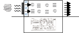 |
Separation of electronic parts | In each module the forced air is filtered at the entrance and is never in touch with the electronic parts. |
 |
Ripple content | The residual ripple measured is less than 2% (1% on request). |
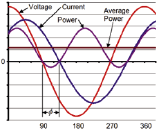 |
Phase shift (Cos Ø) | Phase sift is 0.99 so it does not require systems of rephasing. |
 |
Independent modules operation | Each module is independent of the others and can assume both master and slave configuration. If in slave configuration can be turned off and dispensing is guaranteed by the other modules. The master can never be off, but a slave can become a master. |
 |
Electronic card replacement | Each module has only one electronic card with all the functions of the rectifier. The replacement is a lot easy and can be done by a normal maintenance technician. Movie on www.powerel.it |
 |
Power module replacement | It is also easy to replace an entire module by a normal maintenance technician. Video on www.powerel.it |
MULTIMEDIA 
Power Module Replacement |
Replacing power card |
