


Case P10

Case P13
Case T1-T10

Case W1-W8

Reverse polarity
Reverse polarity is necessary when both direct and inverse voltages (anodic attack) must be injected into the same bath. Powerel realizes this type of rectifiers, interposing one or more reverse modules in the rectifier structure. All the reverse modules are static with the use of MOSFET and controlled by the machine CANBUS allowing inversion times extremely fast. In the modular rectifiers each inversion module supports a maximum current of 1000 Amp if air cooled and 1250 Amp if water cooled.
Full reverse
It is the classical construction where the same quantity of current is requested in DIRECT and REVERSE mode. To exemplify if is required 10000 Amp direct and 10000 Amp reverse, the rectifier will be provided with 10 modules with direct current and 10 reverse, total 20 modules.
Parzial reverse
If need to have a lower REVERSE current than the DIRECT current, Powerel is able to construct a rectifier in able to meet this need. The saving compared to one with total inversion is particularly noticeable where the difference between DIRECT and INVERSE it is remarkable. To exemplify if 10000 Amp direct are rquested and 3000 Amp reverse only, will be realized a rectifier with 10 modules with direct current and 3 inversion only, total 13 modules.
Technical Data
| Power supply | Threephase 400 VAC without neutral |
| Currents supplied for module | MAX 1000 A |
| Voltages supplied for module | MAX 100 V |
| Power for module | MAX 16 kW |
| Controlled modules (parallel or series) |
MAX 32 |
| Modules for tower | Max 10, suggested 6 for transport limit |
| Standard efficiency | 85% |
| Maximum efficiency | 88% |
| Range power adjustment | 2% ÷ 100% |
| Ripple | <= 2% (<1% on demand) |
| Dielectric insulation | 3500 V RMS |
| Serial connection | Profinet, Profibus, Canopen, RS485 ASCII, RS485 Modbus-RTU, RS232, 0-10V, 0-20mA |
| Max environment themperature | 40° C |
| Maximum humidity | 85% |
| Protection and maintenance | Short circuit, over temperature, electronic cards tropicalisation, epoxy painted or zinc plated metal parts, air filters (if expected), electronics part protection. |
| Cooling | Air forced |
| Protection and maintenance | It is always possible to add one or more modules to increase the power of the rectifier. |
| Integrated electronic | All the electronic of the rectifier is contained in only one card easily replaceable. |
Weight and Dimensions
| From | To | Case | Dimensions w, d, h | Weight | |
|---|---|---|---|---|---|
| 100 A - 6 V | 100 A - 20 V | P10 | 250 x 585 x 250 mm | 27 kg | |
| 200 A - 6 V | 200 A - 20 V | P13 | 280 x 610 x 387 mm | 38 kg | |
| 500 A - 6 V | 500 A - 20 V | T1 | 545 x 715 x 460 mm | 84 kg | |
| 1000 A - 6 V | 1000 A - 20 V | T2-T10 | 545 x 715 x 240 mm | 60 kg | |
| 500 A - 6 V | 500 A - 20 V | W1 | 545 x 715 x 460 mm | 84 kg | |
| 1250 A - 6 V | 1250 A - 20 V | W2-W8 | 545 x 715 x 240 mm | 60 kg |
(Example of configurations, other solutions available)
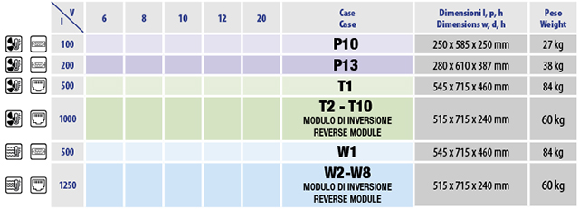
(Each reverse module supports the same maximum current and require the same space as a relative power module. For the correct dimensioning of the rectifiers add to the required power modules the necessary inversion modules and refer to the table in the chapter «Modular rectifiers».)
